
Acquisition of EEG signals using biomedical systems
Procedure for Unipolar (Referential) Montage
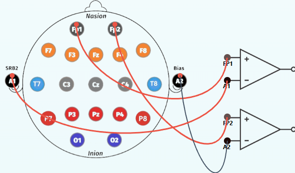
1. For Prefrontal Lobe (Fp1, Fp2)
Step 1:
Click on the EEG cap to start making connections.
Step 2: Establish connections
- Connect Fp1 lead point of human brain to the positive terminal (Fp1) of op-amp circuit.
- Connect Fp2 lead point of human brain to the positive terminal (Fp2) of op-amp circuit.
- Connect Ground lead point A1 of human brain to the negative terminal (A1) of op-amp circuit.
- Connect Ground lead point A2 of human brain to the negative terminal (A2) of op-amp circuit.
Step 3:
Refer to the accompanying figure for correct connection points.
Step 4:
Select an EEG Signal Mode from the dropdown menu:
- Normal
- Eye Blink
- Jaw Clenching
- Forearm Muscle Contraction
Step 5:
Click the Check button to verify correct connections.
Step 6:
If the connection check indicates an error, click the Reset button.
Step 7:
Click the Show Signal button to display the simulated EEG waveform.
Step 8:
Click the Print button to save the recorded observations.
Step 9:
Select another lobe from the left panel to record EEG Signals for its corresponding lobes.
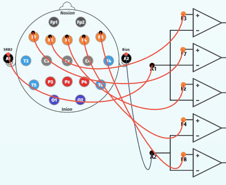
2. For Frontal Lobe (F3, F4, F7, F8, Fz)
Step 1:Click on the EEG cap to start making connections.
Step 2: Establish connections
- Connect F3 lead point of human brain to the positive terminal (F3) of op-amp circuit.
- Connect F4 lead point of human brain to the positive terminal (F4) of op-amp circuit.
- Connect F7 lead point of human brain to the positive terminal (F7) of op-amp circuit.
- Connect F8 lead point of human brain to the positive terminal (F8) of op-amp circuit.
- Connect Fz lead point of human brain to the positive terminal (Fz) of op-amp circuit.
- Connect Ground lead point A1 of human brain to the negative terminal (A1) of op-amp circuit.
- Connect Ground lead point A2 of human brain to the negative terminal (A2) of op-amp circuit.
Step 3:
Refer to the accompanying figure.
Step 4:
Select an EEG Signal Mode from the dropdown menu:
- Normal
- Eye Blink
- Jaw Clenching
- Forearm Muscle Contraction
Step 5:
Click the Check button to verify correct connections.
Step 6:
If the connection check indicates an error, click the Reset button.
Step 7:
Click the Show Signal button to display the simulated EEG waveform.
Step 8:
Click the Print button to save the recorded observations.
Step 9:
Select another lobe from the left panel to record EEG Signals for its corresponding lobes.
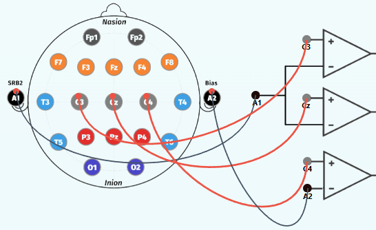
3. For Central Lobe (C3, C4, Cz)
Step 1:
Click on the EEG cap to start making connections.
Step 2: Establish connections
- Connect C3 lead point of human brain to the positive terminal (C3) of op-amp circuit.
- Connect C4 lead point of human brain to the positive terminal (C4) of op-amp circuit.
- Connect Cz lead point of human brain to the positive terminal (Cz) of op-amp circuit.
- Connect A1 lead point of human brain to the negative terminal (A1) of op-amp circuit.
- Connect A2 lead point of human brain to the negative terminal (A2) of op-amp circuit.
Step 3:
Refer to the accompanying figure for correct connection points.
Step 4: Select an EEG Signal Mode from the dropdown menu:
- Normal
- Eye Blink
- Jaw Clenching
- Forearm Muscle Contraction
Step 5:
Click the Check button to verify correct connections.
Step 6:
If the connection check indicates an error, click the Reset button.
Step 7:
Click the Show Signal button to display the simulated EEG waveform.
Step 8:
Click the Print button to save the recorded observations.
Step 9:
Select another lobe from the left panel to record EEG Signals for its corresponding lobes.
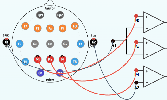
4. For Parietal Lobe (P3, P4, Pz)
Step 1: Click on the EEG cap to start making connections.
Step 2: Establish connections
- Connect P3 lead point of human brain to the positive terminal (P3) of op-amp circuit.
- Connect P4 lead point of human brain to the positive terminal (P4) of op-amp circuit.
- Connect Pz lead point of human brain to the positive terminal (Pz) of op-amp circuit.
- Connect A1 lead point of human brain to the negative terminal (A1) of op-amp circuit.
- Connect A2 lead point of human brain to the negative terminal (A2) of op-amp circuit.
Step 3: Refer to the accompanying figure for correct connection points.
Step 4: Select an EEG Signal Mode from the dropdown menu:
- Normal
- Eye Blink
- Jaw Clenching
- Forearm Muscle Contraction
Step 5: Click the Check button to verify correct connections.
Step 6: Click the Reset button if the connection check indicates an error.
Step 7: Click the Show Signal button to display the simulated EEG waveform.
Step 8: Click the Print button to save the recorded observations.
Step 9: Select another lobe from the left panel to record EEG Signals for its corresponding lobes.
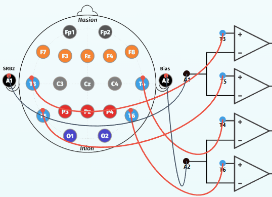
5. For Temporal Lobe (T3, T4, T5, T6)
Step 1: Click the EEG cap to start making connections .
Step 2: Establish connections
- Connect T3 lead point of human brain to the positive terminal (T3) of op-amp circuit.
- Connect T4 lead point of human brain to the positive terminal (T4) of op-amp circuit.
- Connect T5 lead point of human brain to the positive terminal (T5) of op-amp circuit.
- Connect T6 lead point of human brain to the positive terminal (T6) of op-amp circuit.
- Connect A1 lead point of human brain to the negative terminal (A1) of op-amp circuit.
- Connect A2 lead point of human brain to the negative terminal (A2) of op-amp circuit.
Step 3:
Refer to the accompanying figure for correct connection points.
Step 4: Select an EEG Signal Mode from the dropdown menu:
- Normal
- Eye Blink
- Jaw Clenching
- Forearm Muscle Contraction
Step 5: Click the Check button to verify correct connections.
Step 6: Click the Reset button if the connection check indicates an error.
Step 7: Click the Show Signal button to display the simulated EEG waveform.
Step 8: Click the Print button to save the recorded observations.
Step 9: Select another lobe from the left panel to record EEG Signals for its corresponding lobes.
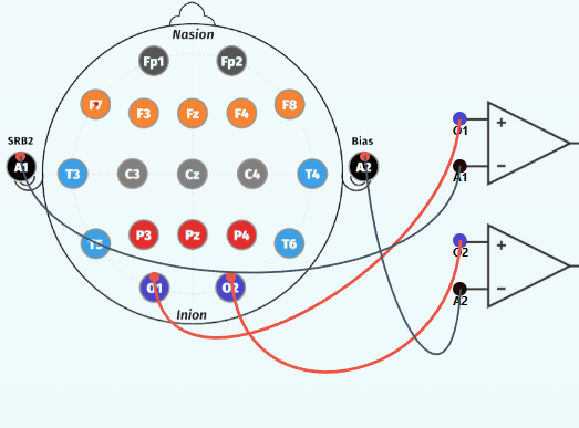
6. For Occipital Lobe (O1, O2)
Step 1: Click EEG cap to start making connections.
Step 2: Establish connections
- Connect O1 lead point of human brain to the positive terminal (O1) of op-amp circuit.
- Connect O2 lead point of human brain to the positive terminal (O2) of op-amp circuit.
- Connect A1 lead point of human brain to the negative terminal (A1) of op-amp circuit.
- Connect A2 lead point of human brain to the negative terminal (A2) of op-amp circuit.
Step 3: Refer to the accompanying figure for correct connection points.
Step 4: Select an EEG Signal Mode from the dropdown menu:
- Normal
- Eye Blink
- Jaw Clenching
- Forearm Muscle Contraction
Step 5: Click the Check button to verify correct connections.
Step 5: Click the Check button to verify correct connections.
Step 6: Click the Reset button if the connection check indicates an error.
Step 7: Click the Show Signal button to display the simulated EEG waveform.
Step 8: Click the Print button to save the recorded observations.
Step 9: Select another lobe from the left panel to record EEG Signals for its corresponding lobes.
Procedure for Bipolar (Anterior–Posterior) Montage
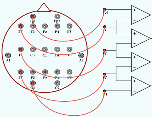
1. For Left Temporal Chain( Fp1-F7-T3-T5-O1):
Step 1: Establish connections
- Connect Fp1 lead point of human brain to the positive terminal (Fp1) of first op-amp circuit.
- Connect F7 lead point of human brain to the terminal (F7) of op-amp circuit.
- Connect T7 lead point of human brain to the terminal (T7) of op-amp circuit.
- Connect P7 lead point of human brain to the terminal (P7) of op-amp circuit.
- Connect O1 lead point of human brain to the negative terminal (O1) of op-amp circuit.
Step 2: Refer to the accompanying figure for correct connection points.
Step 3: Click the Check button to verify correct connections.
Step 4:If the connection check indicates an error, click the Reset button to clear all the connections and restart the process.
Step 5: Click the Show Signal button to display EEG waveform.
Step 6: Click the Print button to save the recorded observations.
Step 7: Select another Channel from the left panel to record EEG Signals for its corresp nding Channel.
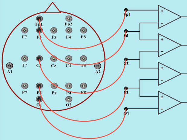
2. For Left Central Chain( Fp1-F3-C3-P3-O1):
Step 1: Establish connections
- Connect Fp1 lead point of human brain to the positive terminal (Fp1) of first op-amp circuit.
- Connect F3 lead point of human brain to the terminal (F3) of op-amp circuit.
- Connect C3 lead point of human brain to the terminal (C3) of op-amp circuit.
- Connect P3 lead point of human brain to the terminal (P3) of op-amp circuit.
- Connect O1 lead point of human brain to the negative terminal (O1) of op-amp circuit.
Step 2: Refer to the accompanying figure for correct connection points.
Step 3: Click the Check button to verify correct connections.
Step 4:If the connection check indicates an error, click the Reset button to clear all the connections and restart the process.
Step 5: Click the Show Signal button to display EEG waveform.
Step 6: Click the Print button to save the recorded observations.
Step 7: Select another Channel from the left panel to record EEG Signals for its corresp nding Channel.
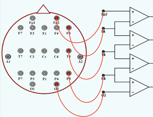
3. For Right Temporal Chain( Fp2-F8-T4-T6-O2):
Step 1: Establish connections
- Connect Fp2 lead point of human brain to the positive terminal (Fp2) of first op-amp circuit.
- Connect F8 lead point of human brain to the terminal (F8) of op-amp circuit.
- Connect T4 lead point of human brain to the terminal (T4) of op-amp circuit.
- Connect T6 lead point of human brain to the terminal (T6) of op-amp circuit.
- Connect O2 lead point of human brain to the negative terminal (O2) of op-amp circuit.
Step 2: Refer to the accompanying figure for correct connection points.
Step 3: Click the Check button to verify correct connections.
Step 4:If the connection check indicates an error, click the Reset button to clear all the connections and restart the process.
Step 5: Click the Show Signal button to display EEG waveform.
Step 6: Click the Print button to save the recorded observations.
Step 7: Select another Channel from the left panel to record EEG Signals for its corresp nding Channel.
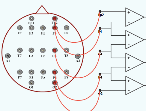
4. For Right Central Chain( Fp2-F4-C4-P4-O2):
Step 1: Establish connections
- Connect Fp2 lead point of human brain to the positive terminal (Fp2) of first op-amp circuit.
- Connect F4 lead point of human brain to the terminal (F4) of op-amp circuit.
- Connect C4 lead point of human brain to the terminal (C4) of op-amp circuit.
- Connect P4 lead point of human brain to the terminal (P4) of op-amp circuit.
- Connect O2 lead point of human brain to the negative terminal (O2) of op-amp circuit.
Step 2: Refer to the accompanying figure for correct connection points.
Step 3: Click the Check button to verify correct connections.
Step 4:If the connection check indicates an error, click the Reset button to clear all the connections and restart the process.
Step 5: Click the Show Signal button to display EEG waveform.
Step 6: Click the Print button to save the recorded observations.
Step 7: Select another Channel from the left panel to record EEG Signals for its corresp nding Channel.
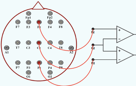
5. For Midline Chain Lobe( Fz-Cz-Pz):
Step 1: Establish connections
- Connect Fz lead point of human brain to the positive terminal (Fz) of first op-amp circuit.
- Connect Cz lead point of human brain to the terminal (Cz) of op-amp circuit.
- Connect Pz lead point of human brain to the terminal (Pz) of op-amp circuit.
- Connect O1 lead point of human brain to the negative terminal (O1) of op-amp circuit.
Step 2: Refer to the accompanying figure for correct connection points.
Step 3: Click the Check button to verify correct connections.
Step 4:If the connection check indicates an error, click the Reset button to clear all the connections and restart the process.
Step 5: Click the Show Signal button to display EEG waveform.
Step 6: Click the Print button to save the recorded observations.
Step 7: Select another Channel from the left panel to record EEG Signals for its corresp nding Channel.